 PDF
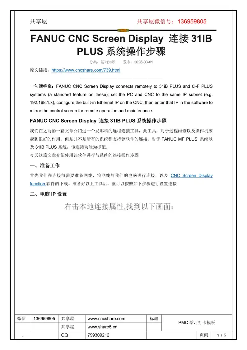
FANUC CNC Screen Display 连接31IBPLUS 系统操作步骤
FANUC CNC Screen Display connects remotely to 31iB PLUS and 0i-F PLUSsystems (a standard feature on these); set the PC and CNC to the same IP subnet (e.g.192.168.1.x), configure the built-in Ethernet IP on the CNC, then enter that IP in the software tomirror the control screen for remote operation and maintenance.FANUC
原版 PDF 下载通道暂未开放,可在线阅读全文;后续开放后此处会自动启用。
文档简介
CNC 系统与功能FANUC CNC Screen Display connects remotely to 31iB PLUS and 0i-F PLUS systems (a standard feature on these); set the PC and CNC to the same IP subnet (e.g. 192.168.1.x), configure the built-in Ethernet IP on the CNC, then enter that IP in the software to mirror the control screen for remote operation and maintenance. FANUC CNC Screen Display 连接31IB PLUS 系统操作步骤我们在之前的一篇文章介绍过一个发那科的远程连接工具,此工具,对于远程维修以及操作机床起到很好的作用,但是并不是所有的
本文档共 5 页,整理自 www.cncshare.com,原文链接:https://www.cncshare.com/739.html。本站提供逐页在线阅读,便于在手机与电脑上对照现场排查。
📖 展开文字版全文(共 5 页,便于复制与检索)
第 1 页
www.share5.cn
FANUC CNC Screen Display 连接31IB
PLUS 系统操作步骤
分类:基础知识发布:2026-03-09
原文链接:https://www.cncshare.com/739.html
一句话答案:FANUC CNC Screen Display connects remotely to 31iB PLUS and 0i-F PLUS
systems (a standard feature on these); set the PC and CNC to the same IP subnet (e.g.
192.168.1.x), configure the built-in Ethernet IP on the CNC, then enter that IP in the software to
mirror the control screen for remote operation and maintenance.
FANUC CNC Screen Display 连接31IB PLUS 系统操作步骤
我们在之前的一篇文章介绍过一个发那科的远程连接工具,此工具,对于远程维修以及操作机床
起到很好的作用,但是并不是所有的系统都支持该软件的连接,对于FANUC MF PLUS 系统以
及31IB PLUS 系统,该连接功能为标配。
今天这篇文章介绍使用该软件进行与系统的连接操作步骤
一、准备工作
首先我们在连接前需要准备网线,将网线与我们的电脑进行连接,以及CNC Screen Display
function 软件的下载。准备好以上工具后,就可以按照如下步骤进行设置连接
二、电脑IP 设置
第 2 页
www.share5.cn
在此界面设置连接的IP 地址,需要与系统保持在一个网段中
三、发那科系统设置
如下图所示,在系统内置以太网界面设定系统IP 地址,这里设置192.168.1.1
第 3 页
www.share5.cn
第 4 页
www.share5.cn
FANUC CNC Screen Display 软件设置
然后我们打开软件连接界面,如下所示,设定连接的IP 地址,这里设置为192.168.1.1
第 5 页
www.share5.cn
常见问题
这类问题现场应该怎么快速定位?
建议按「先看现象、再定地址、后查时序」的顺序:先确认故障是偶发还是必现,再定位到具体
地址,最后用梯形图逐条核对执行时序。
排查时应该以什么为准?
以现场实测为准,不是以程序为准。顺序是电气图 / 地址表 → 现场实测 → 梯形图程序,顺序
反了越改越偏。
修改后如何验证是否真正解决?
做完整记录:改前记录相关状态,改后重启立即读取同一批地址比对。地址应以后台实测为准,
不要套用理论结论。
同专题推荐
查看全部 →



使用说明
本文档仅作技术参考。不同系列、不同机床厂的配置存在差异,号段与位定义请以本机画面及对应系列官方手册为准;改动参数、PMC 程序或硬件接线前请先备份,并由具备资质的人员操作。内容版权归 www.cncshare.com 所有,转载请先联系作者。