


In order to improve the accuracy of the machine tool, sometimes we need to add a full closed loop to the machine tool, which is to add feedback from a grating ruler. Of course, there are many types of grating rulers, such as Heidelberg, Farge, and so on. When configuring a full closed loop grating ruler, we need to know the specific data below in order to debug the machine tool
1. Model of grating ruler
2. Number and connection sequence of grating rulers for machine tool configuration
The specific setting of the grating ruler can be roughly divided into two steps. The first step is to set the FSSB. The second step is to set the position feedback and transmission ratio related parameters
The following is a case study of a machine tool for relevant settings, which you can refer to
Machine configuration X Y Z A C SP, where the spindle is a simulated spindle
一、Separate Detector Unit
In a fully closed-loop machine tool, an independent detector or grating ruler needs to be used to provide feedback on the actual position of the machine tool to improve the accuracy of the machine tool. Stand-alone detector or grating
The feedback signal of the ruler is input through a separate detector and communicates with the system through an optical cable (FSSB) to transmit position information.
According to the type of feedback signal, the separate detection unit is divided into an interface for receiving TTL square wave signals and an interface for receiving 1VPP analog signals.

Separate Detector Unit
Position detector interface unit A02B-0323-C205
二、Set FSSB parameters

How to Add Full Closed Loop to Fanuc System?
SET 1902#0 TO 1
#0 FMD The FSSB setting mode is:
0: Automatic setting mode.
(When the relationship between an axis and amplifier is defined on the FSSB settingscreen, parameter No.1023, bit 0 of parameter No.2013, parameter No.3717, bit 4 of
parameter No.11802 and parameters 24000 to 24103 are automatically set.
1: Manual setting 2 mode.
(parameter No.1023, bit 0 of parameter No.2013, parameter No.3717, bit 4 ofparameter No.11802 and parameters 24000 to 24103 are to be manually set.)
三、Setting 24000 PARAMETERS OF FSSB
24000—24031 ATR value corresponding to slave 01 on first FSSB line
1001 to 1046, 2001 to 2016, 3001 to 3004, 1000
Each of these parameters sets the value (ATR value) of the address translation tablecorresponding to each of slave 1 to slave 32 on first FSSB line (first optical connector).
The slave is a generic term for servo amplifiers, spindle amplifiers and separate detectorinterface units connected via an FSSB optical cable to the CNC. Numbers 1 to 32 are assigned to slaves, with younger numbers sequentially assigned to slaves closer to the
CNC. A 2-axis amplifier consists of two slaves, and a 3-axis amplifier consists of three slaves. In each of these parameters, set a value as described below, depending on whether theslave is an amplifier, separate detector interface unit, or nonexistent.
• When the slave is a servo amplifier:
Set the axis number of a servo amplifier to allocate (value set with parameter No.1023) plus 1000.
• When the slave is a spindle amplifier:
Set the spindle number of a spindle to allocate (value set with parameter No. 3717)plus 2000.
• When the slave is a separate detector interface unit:
Set 3001, 3002, 3003, and 3004, respectively, for the first (one connected nearest to
the CNC), second, third, and fourth separate detector interface units.
• When the slave is nonexistent: Set 1000.
Example of axis configuration and parameter settings
![图片[3]-How to Add Full Closed Loop to Fanuc System? - FANUC CNC-FANUC CNC](https://www.share5.cn/wp-content/uploads/2024/04/1713965838812.png)
For this Machine:
24000 1001
24002 1002
24003 1003
24004 1004
24005 1005
24006 3001 SDU
四、Setting 24096 TO 24103
Connector number for the first or ninth separate detector interface unit
Set a connector number for the connector to which a separate detector interface unit isattached if the separate detector interface unit is to be used. The following table lists the necessary settings. Be sure to specify 0 for connectors not in use.
![图片[4]-How to Add Full Closed Loop to Fanuc System? - FANUC CNC-FANUC CNC](https://www.share5.cn/wp-content/uploads/2024/04/1713966083711.png)
![图片[5]-How to Add Full Closed Loop to Fanuc System? - FANUC CNC-FANUC CNC](https://www.share5.cn/wp-content/uploads/2024/04/1713966125006.png)
After restarting, check whether the FSSB setting is correct and whether the grating ruler module is recognized. If the grating scale module is not recognized, check whether the optical cable connection is correct and the grating scale wire connection is correct. Repeat steps 2-4 above. If the grating scale module is recognized
五、Set servo parameters
-
set 1815#1 to 1
![图片[6]-How to Add Full Closed Loop to Fanuc System? - FANUC CNC-FANUC CNC](https://www.share5.cn/wp-content/uploads/2024/04/1714136271198.png)
#1 OPTx The separate position detector is:
0: Not to be used (semi-closed system)
1: To be used (full-closed system)
2、Flexible gear ratio setting
Flexible gear ratio setting value example (N/M)
![图片[7]-How to Add Full Closed Loop to Fanuc System? - FANUC CNC-FANUC CNC](https://www.share5.cn/wp-content/uploads/2024/04/1714136845519.jpg)
Flexible feed gear (N/M) =Minimum resolution of detector [µm] / controller detection unit [µm]
Setting example (1)
Use 0.5μm grating ruler to detect 1μm
For a movement of 1μm, the output pulse of the grating ruler is 1μm/0.5μm = 2 pulses
NC pulse equivalent for position control: output 1 pulse = detection unit is1μm,
so M/N=1/2
3、Number of speed feedback pulses,position feedback pulse number
Speed feedback pulse number=8192
Number of position pulses =Amount of movement per motor revolution [mm] /detection unit of the sensor [mm]
If the result of the above calculation does not fall in the setting range (0 to 32767) for the number of position pulses, use
“position feedback pulse conversion coefficient” to specify the number of position pulses according to the following procedure.
Number of position pulses to be set = A × B
A: Position pulses parameter No.2024 (Series 30i, 16i and so on)
B:Position pulses conversion coefficient parameter No.2185 (Series 30i, 16i and so on)
(Example of parameter setting)
[System configuration]
• The Series 16i is used.
• A linear scale with a minimum resolution of 0.1 µm is used.
• The least input increment of the controller is 1 µm.
• The amount of movement per motor revolution is 16 mm.
[Parameter setting]
• To enable a separate detector, set bit 1 of parameter No. 1815 to1.
• Calculate the parameters for the flexible feed gear.
Because flexible feed gear (N/M) = 0.1 µm/1 µm = 1/10:
No. 2084 = 1 and No. 2085 = 10
• Calculate the number of position pulses.
Number of position pulses = 16 mm/0.0001mm = 160000
Because this result does not fall in the setting range (0 to 32767),set A and B, respectively, with the “number of position pulses”and “position pulses conversion coefficient” by assuming:
160,000 = 10,000 × 16 → A = 10,000 and B = 16 No.2024 = 10,000, No.2185 = 16
4、Reference counter capacity setting
Set the reference counter. Used when performing grid mode reference point return.
Reference counter capacity = number of position pulses required per motor revolution
Setting example
When Z phase interval = 50mm, detection unit = 1μm
Reference counter = 50/0.0001 = 50000
Turn off the power supply to the NC and then turn it back on again. At this point, the initialization settings of the servo are completed.
bundle.
五、Summary of questions:
When debugging the grating ruler, we will always encounter some unexpected problems. The problems encountered in the future will continue to be summarized.
-
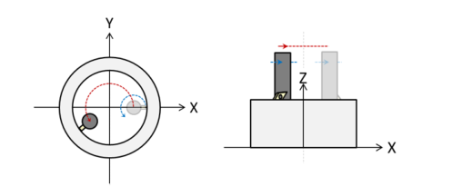
Setting the signal direction of the separate detector
When connecting the separate detector signal in the reverse direction, use the following parameter:
![图片[8]-How to Add Full Closed Loop to Fanuc System? - FANUC CNC-FANUC CNC](https://www.share5.cn/wp-content/uploads/2024/04/1714138553802.png)
RVRSE (#0) The signal direction of the separate detector is:
0: Not reversed.
1: Reversed.


暂无评论内容